Ex. 3: Software development and system simulation
Group: rvlab01
1. Questions
1. to 4: What is the highest speed of the running light your software can handle?
Our software can prevent the pattern from reaching the most and least significan bits of the pattern as long as the number of cycles between each animation step is above 55.
2. to 4: How many clock cycles does your application require for a complete pass of its main loop?
To determine the number of clock cycles for a main loop cycle, the jump address of the beginning of the main loop was determined by looking at jumps in the dissassembly of the software binary. Markers for that PC address can be seen in the follwing image:
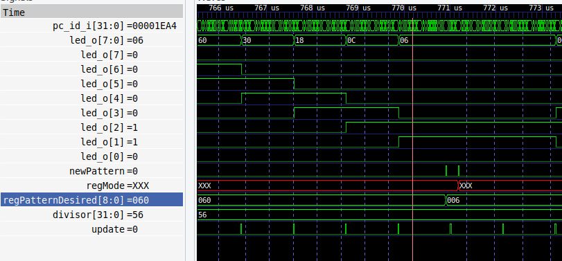
By determining times between the cycles where the code is only checking the pattern and not writing anything, and then dividing by the period of a sys_clk cycle, resulted in an average number of 27 cylcles per loop. A main loop cycle including the writes required for a direction reversal takes approx. 70 sys_clk cycles.
3. to 4: How many clock cycles after the 1st instruction in ctrt0.S is the stack pointer of the IRQ initialized?
The csrrw zero, mscratch, sp command was determined to be the end of the stack pointer of the IRQ initialization. In the wave viewer it can be oberserved that starting at address zero results in a jump to the _start symbol. From there, we can observe the process of setting all 32 internal registers to zero. The address of the _irq_stack_top symbol is then loaded in the CS register.
Measuring the time after the reset is released until lui sp, %hi(_main_stack_top), the instruction after the stack pointer of the IRQ initialization, was reached, resulted in 36 sys_clks for 34 instructions. This shows that only the first two jump instructions need more than one cycle.
2. Deliverables of task 4
1. Register definitions
student_rlight.status @ + 0x0 Status Reset default = 0x0, mask 0xff | ||||||||||||||||||||||||||||||||||||||||||||||||||||||||||||||||||||
|---|---|---|---|---|---|---|---|---|---|---|---|---|---|---|---|---|---|---|---|---|---|---|---|---|---|---|---|---|---|---|---|---|---|---|---|---|---|---|---|---|---|---|---|---|---|---|---|---|---|---|---|---|---|---|---|---|---|---|---|---|---|---|---|---|---|---|---|---|
| ||||||||||||||||||||||||||||||||||||||||||||||||||||||||||||||||||||
| Bits | Type | Reset | Name | Description | ||||||||||||||||||||||||||||||||||||||||||||||||||||||||||||||||
| 7:0 | ro | 0x0 | pattern | Bits of currently displayed LED pattern | ||||||||||||||||||||||||||||||||||||||||||||||||||||||||||||||||
student_rlight.mode @ + 0x4 LED animation mode Reset default = 0x3, mask 0x3 | ||||||||||||||||||||||||||||||||||||||||||||||||||||||||||||||||||||
|---|---|---|---|---|---|---|---|---|---|---|---|---|---|---|---|---|---|---|---|---|---|---|---|---|---|---|---|---|---|---|---|---|---|---|---|---|---|---|---|---|---|---|---|---|---|---|---|---|---|---|---|---|---|---|---|---|---|---|---|---|---|---|---|---|---|---|---|---|
| ||||||||||||||||||||||||||||||||||||||||||||||||||||||||||||||||||||
| Bits | Type | Reset | Name | Description | ||||||||||||||||||||||||||||||||||||||||||||||||||||||||||||||||
| 1:0 | rw | 0x3 | val | 0 = stop, 1 = right-to-left, 2 = left-to-right, 3 = ping-pong | ||||||||||||||||||||||||||||||||||||||||||||||||||||||||||||||||
student_rlight.speed @ + 0x8 Speed register for LED animation Reset default = 0x0, mask 0xffffffff | ||||||||||||||||||||||||||||||||||||||||||||||||||||||||||||||||||||
|---|---|---|---|---|---|---|---|---|---|---|---|---|---|---|---|---|---|---|---|---|---|---|---|---|---|---|---|---|---|---|---|---|---|---|---|---|---|---|---|---|---|---|---|---|---|---|---|---|---|---|---|---|---|---|---|---|---|---|---|---|---|---|---|---|---|---|---|---|
| ||||||||||||||||||||||||||||||||||||||||||||||||||||||||||||||||||||
| Bits | Type | Reset | Name | Description | ||||||||||||||||||||||||||||||||||||||||||||||||||||||||||||||||
| 31:0 | rw | 0x0 | divisor | Divisor of the clock used for animation updates | ||||||||||||||||||||||||||||||||||||||||||||||||||||||||||||||||
student_rlight.pattern @ + 0xc Current write address Reset default = 0x0, mask 0xff | ||||||||||||||||||||||||||||||||||||||||||||||||||||||||||||||||||||
|---|---|---|---|---|---|---|---|---|---|---|---|---|---|---|---|---|---|---|---|---|---|---|---|---|---|---|---|---|---|---|---|---|---|---|---|---|---|---|---|---|---|---|---|---|---|---|---|---|---|---|---|---|---|---|---|---|---|---|---|---|---|---|---|---|---|---|---|---|
| ||||||||||||||||||||||||||||||||||||||||||||||||||||||||||||||||||||
| Bits | Type | Reset | Name | Description | ||||||||||||||||||||||||||||||||||||||||||||||||||||||||||||||||
| 7:0 | rw | 0x0 | pattern | Bits of initial LED pattern | ||||||||||||||||||||||||||||||||||||||||||||||||||||||||||||||||
student_rlight.masks @ + 0x10 Masks to trigger IRQ when the displayed pattern intersects them Reset default = 0x0, mask 0xffff | ||||||||||||||||||||||||||||||||||||||||||||||||||||||||||||||||||||
|---|---|---|---|---|---|---|---|---|---|---|---|---|---|---|---|---|---|---|---|---|---|---|---|---|---|---|---|---|---|---|---|---|---|---|---|---|---|---|---|---|---|---|---|---|---|---|---|---|---|---|---|---|---|---|---|---|---|---|---|---|---|---|---|---|---|---|---|---|
| ||||||||||||||||||||||||||||||||||||||||||||||||||||||||||||||||||||
| Bits | Type | Reset | Name | Description | ||||||||||||||||||||||||||||||||||||||||||||||||||||||||||||||||
| 7:0 | rw | 0x0 | mask 0 | Mask that triggers interrupt 0 | ||||||||||||||||||||||||||||||||||||||||||||||||||||||||||||||||
| 15:8 | rw | 0x0 | mask 1 | Mask that triggers interrupt 1 | ||||||||||||||||||||||||||||||||||||||||||||||||||||||||||||||||
student_rlight.interrupt_status @ + 0x14 Indicates whether interrupts are active. Read to acknowledge interrupts Reset default = 0x0, mask 0x3 | ||||||||||||||||||||||||||||||||||||||||||||||||||||||||||||||||||||
|---|---|---|---|---|---|---|---|---|---|---|---|---|---|---|---|---|---|---|---|---|---|---|---|---|---|---|---|---|---|---|---|---|---|---|---|---|---|---|---|---|---|---|---|---|---|---|---|---|---|---|---|---|---|---|---|---|---|---|---|---|---|---|---|---|---|---|---|---|
| ||||||||||||||||||||||||||||||||||||||||||||||||||||||||||||||||||||
| Bits | Type | Reset | Name | Description | ||||||||||||||||||||||||||||||||||||||||||||||||||||||||||||||||
| 0 | ro | 0x0 | interrupt 0 | IRQ triggered by mask 0 | ||||||||||||||||||||||||||||||||||||||||||||||||||||||||||||||||
| 1 | ro | 0x0 | interrupt 1 | IRQ triggered by mask 1 | ||||||||||||||||||||||||||||||||||||||||||||||||||||||||||||||||
Register usage
All writable registers may be changed at any time. On a mode register change, the pattern will be applied. The speed register value will be applied immediately.
When the mode is changed to stop, the system does not reset the current LEDs (status) and instead stays at the last displayed pattern. On the next mode change, it will reset.
2. source texts of the .c and .h files you created or modified (driver and mini application) yourself (not the generated source files)
These sources can be found in the appendix.
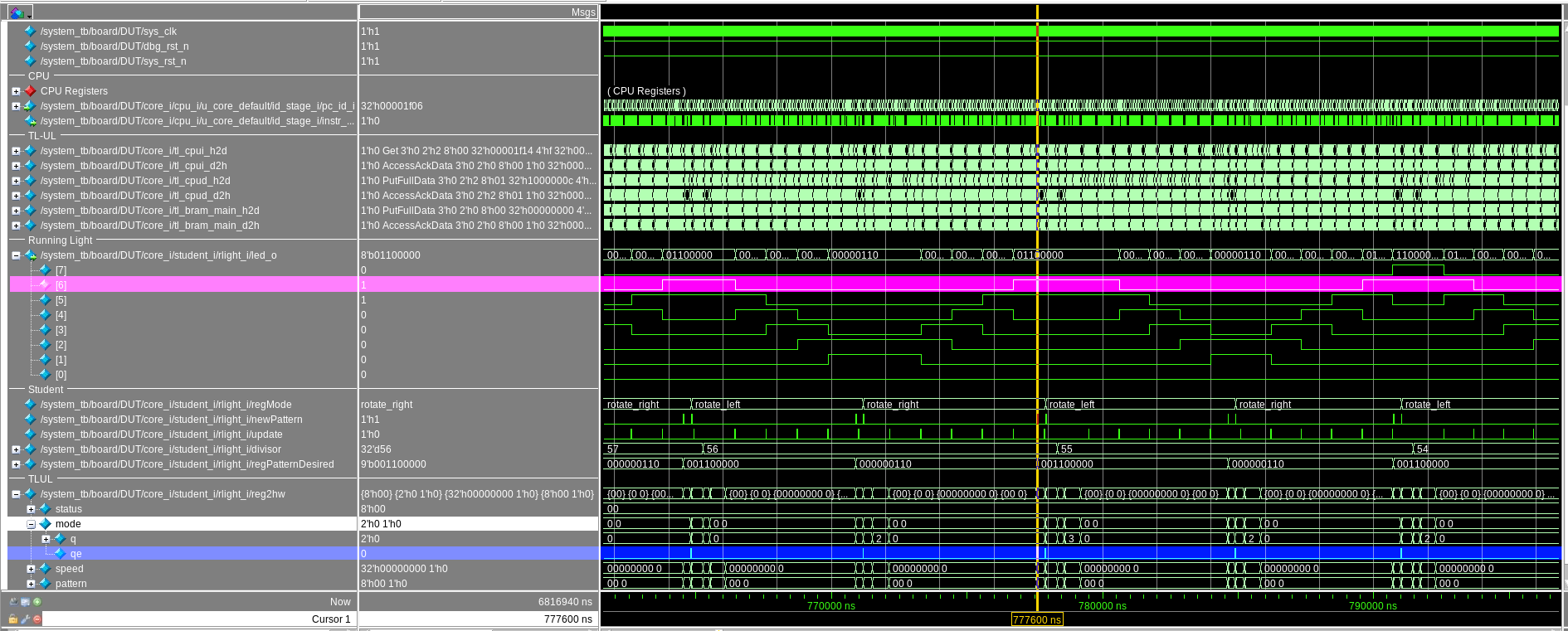
3. a wave view from the system simulation which shows the lightening up of an outermost “grey” LED and the following write access of the software to the mode register
To prevent the LED pattern from reaching the most and least significant bits, the main loop keeps reading the current pattern (status) from the hardware. If a bit in the outermost “grey” positions is detected, the current pattern (status) is written back to the pattern register, to be reapplied once the animation mode is changed. The reversal of the animation direction is completed by writing the inverse rotation mode to the mode register.
The following wave view shows this behavior. The rightmost “gray” LED-bit is highlighted in pink. Directly before the orange cursor, the main loop has detected a necessity to change the direction mode to left. The caused write flag in the mode register is highlighted in blue.
After reducing the number of clocks between each animation step to 55 in the speed register, the software is no longer able to prevent the animation from reaching the most and least significant bits of the pattern.
Appendix:
tinyprintf.c
Added support for binary output format:
                case 'b':
                    p.base = 2;
    #ifdef PRINTF_LONG_SUPPORT
                    if (lng)
                        li2a(va_arg(va, unsigned long int), &p);
                    else
    #endif
                        i2a(va_arg(va, int), &p);
                    written += putchw(putp, &p);
                    break;